Bode Plot MCQ – Control Engineering
Bode Plot Control Engineering MCQ, Bode Plot Multiple Choice Questions, Objective Questions on Bode Plot, Control System MCQ, Bode Plot- Control Engineering MCQ, Engineering MCQ, Control System MCQ
Objective Type Questions and Answers
Q.1. The gain margin (in dB) of a system having the loop transfer function
G(s)H(s)=\frac{\sqrt{2}}{s(s+1)} is
- 0
- 3
- 6
- ∞
Answer: ∞
Q.2. The phase margin (in degrees) of a system having the loop transfer functions
G(s)H(s)=\frac{2\sqrt{3}}{s(s+1)} is
- 45°
- – 30°
- 60°
- 30°
Answer: 30°
Q.3. The phase margin of a system with open loop transfer function
G(s)H(s)=\frac{(1-s)}{(1+s)(2+s)}- 0°
- 63.4°
- 90°
- ∞
Answer: ∞
Q.4. The system with open loop transfer function, G(s)H(s)=\frac{1}{s(s^{2}+s+1)} has a gain margin of
- – 6 dB
- 0 dB
- 3.5 dB
- 6 dB
Answer: 0 dB
Q.5. The approximate Bode magnitude plot of a minimum phase system is shown in the figure below. The transfer of the system is
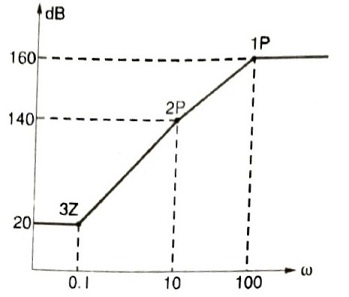
- 10^{8}\frac{(s+0.1)^{3}}{(s+10)^{2}(s+100)}
- 10^{7}\frac{(s+0.1)^{3}}{(s+10)(s+100)}
- 10^{8}\frac{(s+0.1)^{2}}{(s+10)^{2}(s+100)}
- 10^{9}\frac{(s+0.1)^{3}}{(s+10)(s+100)^{2}}
Answer: 10^{8}\frac{(s+0.1)^{3}}{(s+10)^{2}(s+100)}
Q.6. The gain margin and phase margin of a feedback system with G(s)H(s)=\frac{s}{(s+100)^{3}} are
- 0 dB, 0°
- ∞, ∞
- ∞, 0°
- 88.5 dB, ∞
Answer: ∞, ∞
Q.7. The gain margin for the system with open loop transfer function G(s)H(s)=\frac{2(1+s)}{s^{2}} is
- ∞
- 0
- 1
- -∞
Answer: -∞
Q.8. Consider the Bode magnitude plot shown in the figure below. The transfer function H(s) is
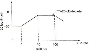
- \frac{(s+10)}{(s+1)(s+100)}
- \frac{10(s-1)}{(s+1)(s+100)}
- \frac{10^{2}(s+1)}{(s+1)(s+100)}
- \frac{10^{3}(s+100)}{(s+1)(s+10)}
Answer: \frac{10^{2}(s+1)}{(s+1)(s+100)}
Q.9. The open loop transfer function of a unity feedback system is given by G(s)=\frac{3e^{-2s}}{s(s+2)}. The gain and phase crossover frequencies are,
- 0.632 and 1.26
- 0.632 and 0.485
- 0.485 and 0.632
- 1.26 and 0.632
Answer: 0.485 and 0.632
Q.10. For the system of the above problem, the gain and phase margin of the system will be
- – 7.09 dB and 87.5°
- 7.09 and 87.5°
- 7.09 dB and – 87.5°
- – 7.09 and – 87.5°
Answer: – 7.09 and – 87.5°
Q.11. The open loop transfer function of a unity feedback control system is given by
G(s)=\frac{K}{(s+1)(s+2)} The gain margin of the system in dB is given by
- 0
- 1
- 20
- ∞
Answer: ∞
Q.12. Consider two transfer functions
G_{1}(s)=\frac{1}{s^{2}+as+b} and G_{2}(s)=\frac{s}{s^{2}+as+b}
The 3 dB band widths of their frequency responses are, respectively
- \sqrt{a^{2}-4b}, \sqrt{a^{2}+4b}
- \sqrt{a^{2}+4b}, \sqrt{a^{2}-4b}
- \sqrt{a^{2}-4b}, \sqrt{a^{2}-4b}
- \sqrt{a^{2}+4b}, \sqrt{a^{2}+4b}
Answer: \sqrt{a^{2}-4b}, \sqrt{a^{2}-4b}
Q.13. Consider a unity feedback control system whose open loop transfer function is
G(s)=\frac{as+1}{s^{2}}The value of “a” so that the system has a phase margin equal to π/4 is approximately equal to
- 2.40
- 1.40
- 0.84
- 0.74
Answer: 0.84
Q.14. With the value of “a” set in above question the value of unit impulse response of the open loop system at t = 1 second is equal to
- 3.40
- 2.40
- 1.84
- 1.74
Answer: 1.84
Q.15. The asymptotic Bode plot of a transfer function is as shown in the figure below. The transfer function G(s) corresponding to this Bode plot is
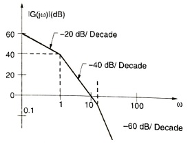
- \frac{1}{(s+1)(s+20)}
- \frac{1}{s(s+1)(s+20)}
- \frac{100}{s(s+1)(s+20)}
- \frac{100}{s(s+1)(1+0.05s)}
Answer: \frac{100}{s(s+1)(1+0.05s)}
Q.16. For the asymptotic bode magnitude plot shown below, the system transfer function can be
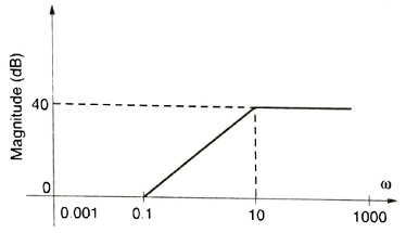
- \frac{10s+1}{0.1s+1}
- \frac{100s+1}{0.1s+1}
- \frac{100s}{10s+1}
- \frac{0.1s+1}{10s+1}
Answer: \frac{10s+1}{0.1s+1}
Q.17. The open loop transfer function of a unity feedback control system is given as
G(s)=\frac{1}{s(1+sT_{1})(1+sT_{2})}The phase crossover frequency and the gain margin are, respectively
- \frac{1}{\sqrt[]{T_{1}T_{2}}} and \frac{T_{1}+T_{2}}{T_{1}T_{2}}
- \sqrt[]{T_{1}T_{2}} and \frac{T_{1}+T_{2}}{T_{1}T_{2}}
- \frac{1}{\sqrt[]{T_{1}T_{2}}} and \frac{T_{1}T_{2}}{T_{1}+T_{2}}
- \sqrt[]{T_{1}T_{2}} and \frac{T_{1}T_{2}}{T_{1}+T_{2}}
Answer: \frac{1}{\sqrt[]{T_{1}T_{2}}} and \frac{T_{1}+T_{2}}{T_{1}T_{2}}
Q.18. An open loop transfer function of a unity feedback control system has two finite zeros, two poles at origin and two pairs of complex conjugate poles. The slope of high frequency asymptote in Bode magnitude plot will be
- + 40 dB/decade
- 0 dB/decade
- – 40 dB/decade
- – 80 dB/decade
Answer: – 80 dB/decade
Q.19. Consider the following open loop frequency response of a unity feedback system:
\begin{matrix} \omega , rad/s\rightarrow : & 2 & 3 & 4 & 5 & 6 & 8 & 10\\ \left | G(j\omega ) \right |\rightarrow : & 7.5 & 4.8 & 3.15 & 2.25 & 1.70 & 1.00 & 0.64\\ \angle G(j\omega )\rightarrow : & -118^{0} & -130^{0} & -140^{0} & -150^{0} & -157^{0} & -170^{0} & -180^{0} \end{matrix}The gain and phase margin of the system are respectively.
- 0.00 dB, – 180°
- 3.86 dB, – 180°
- 0.00 dB, – 10°
- 3.86 dB, 10°
Answer: 3.86 dB, 10°
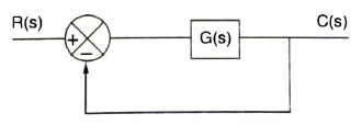
Q.20. Consider the following statements regarding the frequency response of a system as shown below :
- The type of the system is one
- ω3 = static error coefficient (numerically)
- \omega _{2}=\frac{\omega _{1}+\omega _{3}}{2}
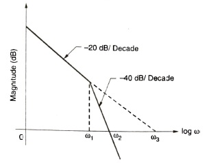
Select the correct answer using the codes given below:
- 1, 2 and 3
- 1 and 2
- 2 and 3
- l and 3
Answer: 1 and 2
Q.21. Consider the unity feedback system with G(s)=\frac{2}{s(s+1)(2s+1)}. What is the gain margin of the system?
- 3/4
- 4/3
- ½
- 3/5
Answer: 3/4
Q.22. Consider the following statements regarding the asymptotic Bode plots used for frequency response analysis:
- The deviation of the actual magnitude response for a zero on the real axis is 3 dB at the corner frequency
- The phase angle for a pair of complex conjugates depends upon the value of the damping ratio.
What of the statements given above is/are correct ?
- Only 1
- Only 2
- Both 1 and 2
- Neither 1 and 2
Answer: Only 1
Q.23. Which one of the following statements is correct for gain margin and phase margin of two closed loop systems having loop functions G(s) H(s) and exp (-s) G(s) H(s) ?
- Both gain and phase margins of the two systems will be identical
- Both gain and phase margins of G(s) H(s) will be more
- Gain margins of the two systems are the same but the phase margin of G(s) H(s) will be more
- Phase margins of the two systems are the same but the gain margin of G(s) H(s) will be less
Answer: Gain margins of the two systems are the same but phase margin of G(s) H(s) will be more
Q.24. The gain-phase plot of a linear control system is shown in the below figure. What are the gain margin (GM) and the phase margin (PM) of the system?
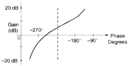
- GM > 0 dB and PM > 0 degree
- GM > 0 dB and PM < 0 degree
- GM < 0 dB and PM > 0 degree
- GM < 0 dB and PM < 0 degree
Answer: GM < 0 dB and PM < 0 degree
Q.25. In the Bode plot a unity feedback control system, the value of phase angle of G(jω) is – 90′ at the gain cross over frequency of the Bode plot, the phase margin of the system is
- – 180°
- + 180°
- – 90°
- + 90°
Answer: + 90°
Related Post: